


Reflection of pressure waves in piping systems
If the characteristic impedance of a pipe changes in the direction in which a wave propagates, reflections occur. In general, a reflection results in the generation of two new waves - a transmitted wave and a reflected wave. Possible causes of impedance changes can be:
- Closed pipe ends
- Open pipe ends, e.g. pipe leading into a large reservoir
- Changes of pipe diameter
- Change of pipe/hose material (e.g. from steel to rubber hose)
- Discrete flow resistances like orifices, valves etc.
- T and Y junctions
- Changes of density and/or speed of sound (e.g. due to thermal effects)
Reflection Factor
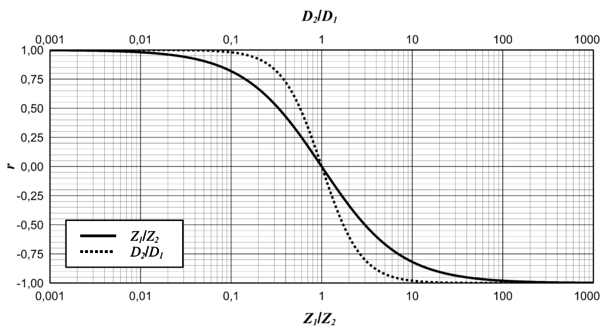
The ratio of the reflected pressure wave \(\delta p_r\) to the incoming pressure wave \(\delta p_e\) is referred to as the reflection coefficient \(r\). It can be calculated from the characteristic impedances before (\(Z_1\)) and after (\(Z_2\)) the impedance change: $$r = \frac{\delta p_r}{\delta p_e} =\frac{Z_2 - Z_1}{Z_2 + Z_1}. $$ The variation of the reflection coefficient \(r\) versus the impedance ratio \(Z_1/Z_2\) or versus the diameter ratio \(D_2/D_1\) is shown in the following figure:

Open End
Since the impedance ratio \(Z_1/Z_2\) tends to infinity for the special case of an open end, the reflection coefficient is \(r \approx -1\). Thus, the reflected wave is exactly equal in magnitude to the incoming wave. The minus sign indicates that the reflected wave travels exactly opposite to the original wave. The returning wave (sum of reflected and incoming wave) results to zero for this case.
Closed End
Since the impedance ratio \(Z_1/Z_2\) tends to zero for the special case of a closed end, the reflection coefficient is \(r \approx 1\). Thus, the reflected wave is equal to the incoming wave with respect to both its magnitude and its sign. The returning wave (sum of reflected and incoming wave) results for this case to \(2\delta p_e\), i.e. twice the magnitude of the incoming wave.
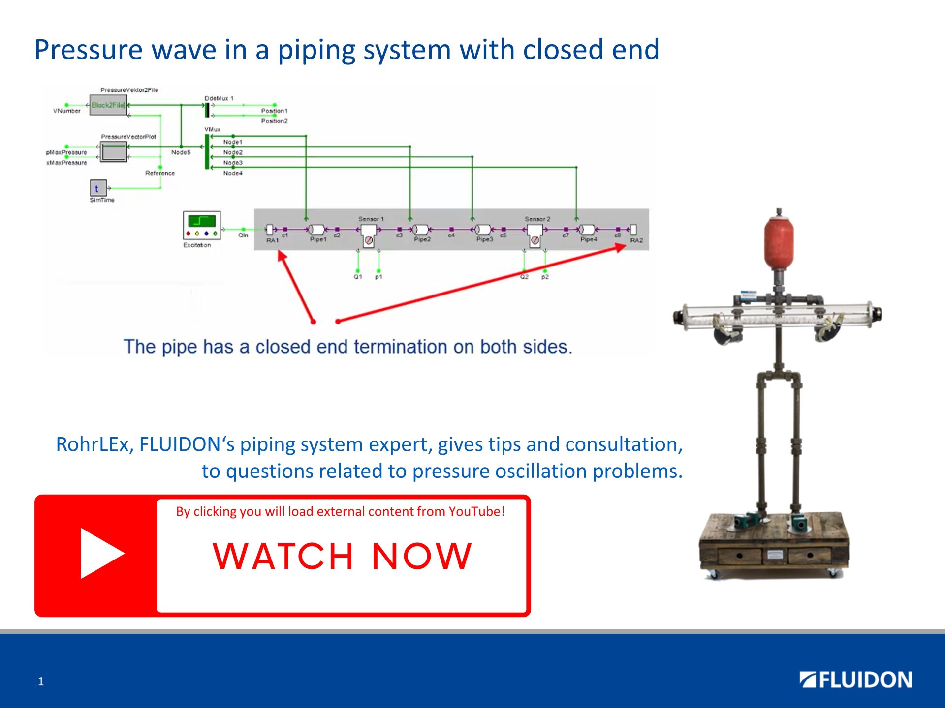
Reflection of a pressure wave at the closed end of a pipe
A pressure oscillation resonance in a pipe closed on both sides, referred to as a closed tube resonance or closed-end resonance, occurs when sound waves within the pipe generate a standing wave pattern due to wave reflections at the closed ends. Here are the key points to understand about it:
-
Standing waves: When a sound wave propagates through a pipe closed on both ends, it undergoes reflection at each end. The resulting interference between the incoming and reflected waves gives rise to a stationary pattern known as a standing wave. Within the pipe, specific locations exhibit points of minimal displacement (nodes) and points of maximal displacement (antinodes).
-
Resonance frequencies: Closed pipe resonance transpires at distinct frequencies associated with the fundamental frequency and its harmonics. The fundamental frequency represents the lowest resonant frequency at which the fluid within the pipe can vibrate. The higher harmonics are integer multiples of the fundamental frequency.
-
Pipe length and resonance: The length of the pipe determines the wavelengths that can fit within it, thereby establishing the frequencies at which resonance occurs. The fundamental frequency in a pipe with both ends closed is inversely proportional to the pipe length. Mathematically, the fundamental frequency (f) is expressed as f = a / (2L), where a represents the speed of sound in the medium and L denotes the length of the pipe.
-
Node and antinode positions: In closed pipe resonance, the closed ends of the pipe function as nodes for the flow, indicating no displacement at these points but as antinodes for the pressure. The positions of nodes and antinodes within the standing wave pattern depend on the resonance mode (fundamental or harmonic) and the pipe length.
-
Sound production: Pressure oscillations occurring within the pipe, resulting from the standing waves, lead to the generation of sound. The pipe acts as a resonator, amplifying specific frequencies dictated by its length.
It is essential to note that the information provided here assumes idealized conditions and simplifications. Real-world scenarios may involve additional factors, such as pipe geometry, wall properties, and damping effects, which can influence the precise behavior of pressure oscillation resonances in closed pipes.
Reflection of a pressure wave at the open end of a pipe
In a pressure oscillation resonance scenario in a pipe that is open at one end and closed at the other, several factors come into play. The phenomenon involves the interaction between the acoustic waves and the geometry of the pipe, leading to the amplification of specific frequencies. Here are some key aspects to consider:
-
Pipe Length: The length of the pipe determines the wavelengths of the resonant frequencies that can be established. A quarter-wavelength resonance occurs when the length of the pipe is equal to one-fourth of the wavelength of the desired resonant frequency.
-
Harmonic Frequencies: The resonance phenomenon can occur at various harmonics of the fundamental frequency. Each harmonic represents a multiple of the fundamental frequency, such as three times, or fife times the fundamental frequency, and so on.
-
Standing Waves: When a pressure oscillation of a specific frequency reaches the closed end of the pipe, it reflects back and interferes with the incident wave. This interference results in the formation of standing waves, where points of maximum and minimum pressure, known as nodes and antinodes, are established along the length of the pipe.
-
Resonant Frequencies: Resonant frequencies are the frequencies at which the standing waves are most pronounced. These frequencies correspond to the natural frequencies at which the pressure oscillations in the pipe reinforce each other, resulting in a significant increase in the amplitude of the waves.
-
Node and Antinode Distribution: The distribution of nodes and antinodes depends on the mode of the standing wave formed. In the fundamental mode (first harmonic), there is, if pressure is considered, one ode at the open end of the pipe and one antinode at the closed end. At higher harmonics, the number of nodes and counter-nodes increases accordingly; these are then located inside the pipe.
It is essential to note that the information provided here assumes idealized conditions and simplifications. Real-world scenarios may involve additional factors, such as pipe geometry, wall properties, and damping effects, which can influence the precise behavior of pressure oscillation resonances in pipes.

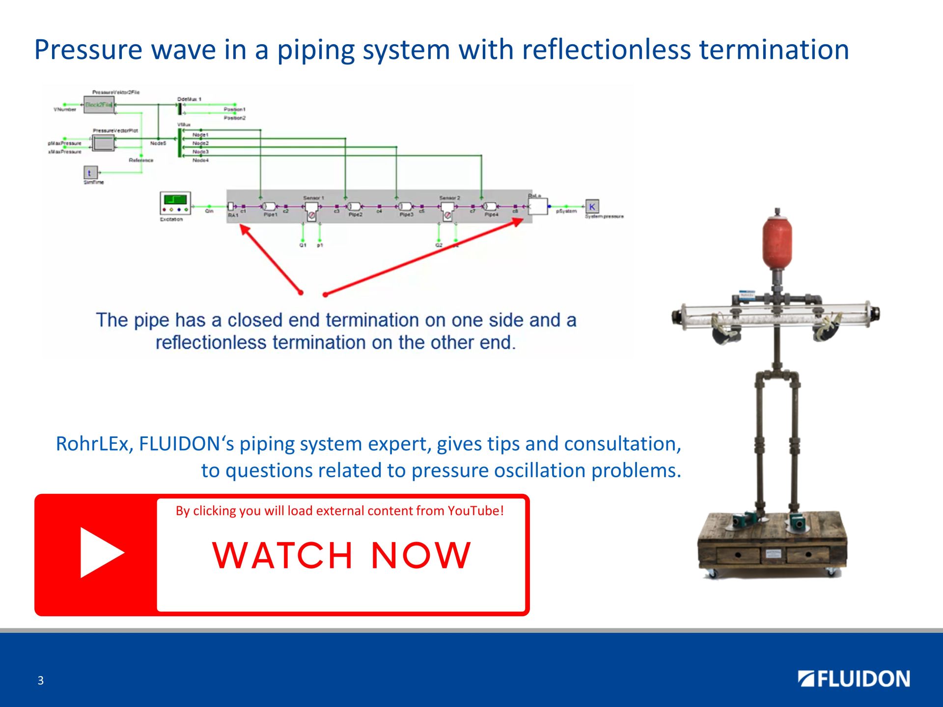
Transition of a pressure wave through a pipe termination with low reflection
A low reflection end condition refers to a situation where the pipe termination minimizes wave reflections, allowing smooth transmission of pressure waves.
When examining pressure pulsation in such a pipe, several key aspects should be considered:
-
Wave Propagation: Pressure pulsation in a pipe can be understood as the propagation of pressure waves generated by various sources, such as pumps, compressors, or fluid flow disturbances. These waves travel through the fluid medium inside the pipe.
-
Wave Reflection: In a low reflection end condition, the termination of the pipe is designed to minimize wave reflections. Ideally, the termination has characteristics that prevent waves from bouncing back into the pipe. This feature reduces the occurrence of pressure pulsations caused by wave reflections.
-
Impedance Matching: The low reflection end condition often involves impedance matching, where the characteristic impedance of the termination closely matches that of the pipe. This matching minimizes the mismatch between the termination and the pipe, reducing the potential for wave reflections.
-
Pressure Attenuation: Despite the low reflection end condition, some pressure pulsations may still exist due to various factors, such as fluid compressibility, pipe friction, or flow instabilities.
By considering these aspects, engineers and researchers can assess the pressure pulsation behavior in pipes with low reflection end conditions, allowing for better design and optimization of fluid systems.
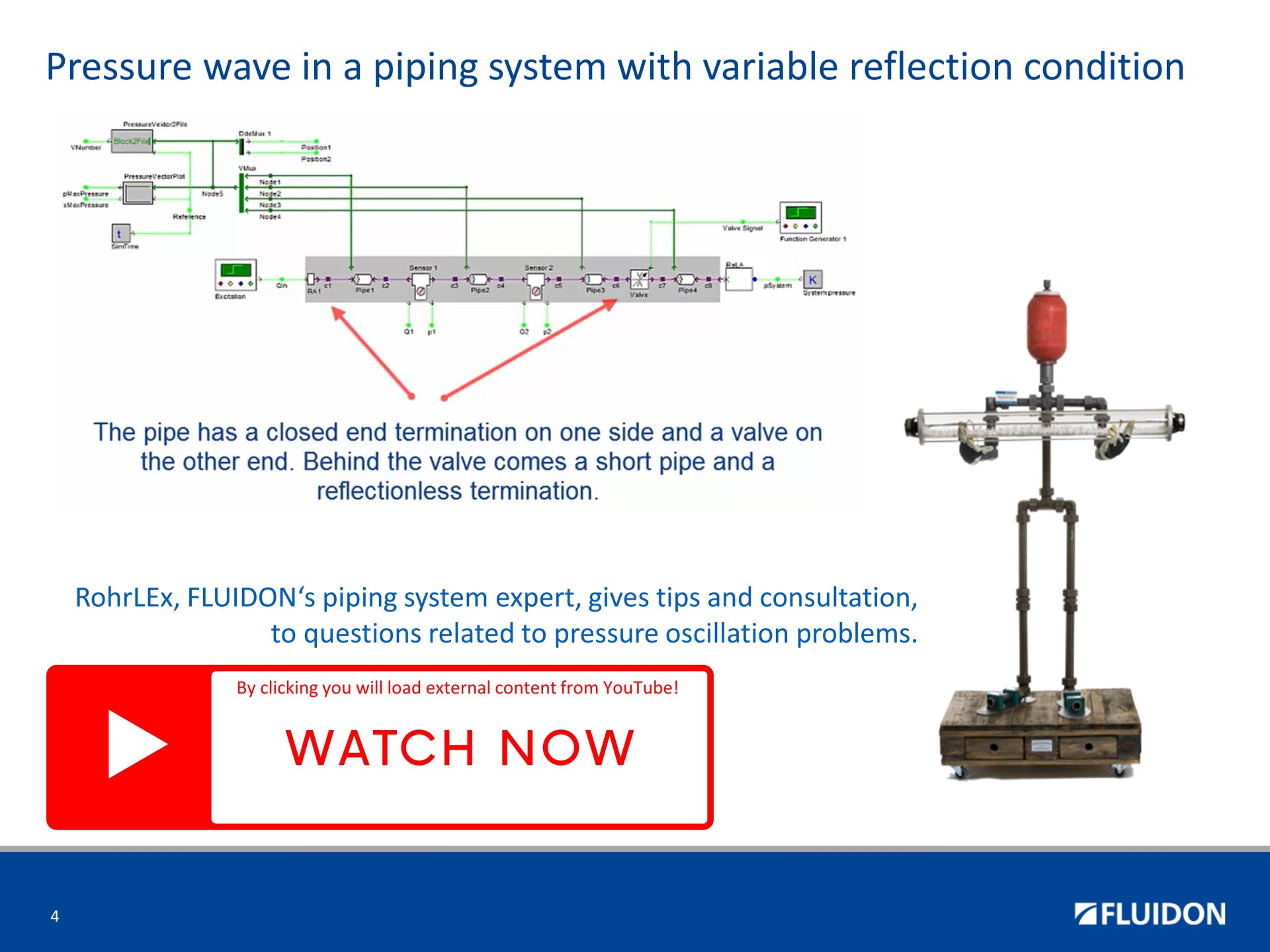
Passage of a pressure wave through a pipe end with variable terminating impedance
In a pipe with variable termination impedance, such as a hydraulic valve, the phenomenon of pressure wave reflection occurs when a pressure wave traveling along the pipe encounters a change in impedance at the termination point.
Here are some key points to consider regarding pressure wave reflection in such a system:
-
Termination Impedance: The termination impedance refers to the characteristic impedance of the hydraulic valve or any other component at the end of the pipe. It represents the opposition to the flow of pressure waves and depends on factors such as valve geometry, material properties, and operating conditions.
-
Incident and Reflected Waves: When a pressure wave propagates along the pipe and reaches the termination point, it encounters the change in impedance. This change causes a portion of the wave to be reflected back into the pipe as a reflected wave. The remaining portion continues past the termination point as the transmitted wave.
-
Reflection Coefficient: The reflection coefficient quantifies the ratio of the amplitude of the reflected wave to that of the incident wave. It is influenced by the mismatch between the characteristic impedance of the pipe and the termination impedance. A reflection coefficient of zero indicates complete transmission, while a value of one indicates complete reflection.
-
Effects of Reflection: The reflection of pressure waves can lead to various effects, including pressure oscillations, energy losses, and potential damage to the system. These effects depend on the magnitude of the reflection coefficient, the wave frequency, and the characteristics of the termination impedance.
-
Standing Waves: In cases where the incident and reflected waves interfere constructively or destructively, standing waves can form within the pipe. Standing waves are stationary patterns of high and low pressure regions that can cause pressure variations and affect the system's performance.
-
Impedance Matching: Proper impedance matching between the pipe and the termination impedance can minimize pressure wave reflections. By adjusting the termination impedance to match the characteristic impedance of the pipe, the reflection coefficient can be reduced, leading to improved system efficiency and reduced pressure fluctuations.
Through careful consideration of impedance matching and system dynamics, engineers can mitigate the negative effects of pressure wave reflections and enhance the overall performance of hydraulic systems. A theoretical example of a matched impedance is presented here. A FLUIDON's Rala is practical example of a matheched impedance.
Reflection of a pressure wave at the impedance change between the pipe and flexible hose
When a pressure wave travels through a pipe and encounters a change in pipe geometry or a change in pipe material, the phenomenon of reflection occurs. The reflection of the pressure wave can be explained by the principles of fluid dynamics.
- When the pressure wave reaches the area of change (diameter, wall thickness, material properties), a portion of the wave is transmitted through, while another portion is reflected back towards the source. The reflection occurs due to the change in the acoustic impedance. The acoustic impedance is determined by the product of fluid density and sounic velocity devided by the cross sectual area.
- The magnitude and nature of the reflection depend on various factors, such as the angle of incidence, the magnitude of the change in diameter, and the properties of the fluid.
- In general, a sudden expansion (increase in diameter) leads to a reflection of a negative pressure wave, while a sudden contraction (decrease in diameter) causes a positive reflection.
- The reflected wave propagates back towards the source and interacts with the incident wave. The interaction results in interference patterns, where the superposition of the incident and reflected waves leads to constructive or destructive interference. The specific interference pattern depends on the phase relationship between the incident and reflected waves.
