


Pressure oscillation analysis of hydraulic pipework systems
For the conception of remedies for pressure oscillation problems the knowledge of the system's critical frequencies and the exact localization of areas of high and low pressure fluctuations is a prerequisite for the right positioning of the remedies within the line system.
For the analysis of the oscillation situation, RohrLEx uses the visualization of the pressure pulsations along the middle axis of the pipe line system.

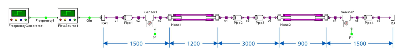
By means of an example piping system, RohrLEx describes the typical procedure for this kind of analysis. The piping system example with a total length of 8.1 m consists of three steel pipe segments and two flexible hose lines.
If it comes to pressure pulsation problems in a piping system, usually only the signals of pressure sensors distributed over the plant are available for the examination of the oscillation situation. This is indicated in the example piping system by two sensor components. With these pressure signals one is able to find the frequencies of the oscillation - in the spectrum of the pressure signals these are e.g. the main frequencies 65 Hz, 157 Hz and 330 Hz -, it is however for RohrLEx very difficult, to draw conclusions about the waveform and the interactions within the piping system.
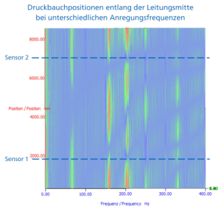
If the piping system becomes, however, examined through simulation, additional information for the oscillation analysis is available for RohrLEx. By visualizing the pressure pulsations in the so-called "pressure vector plot", RohrLEx gets an overview of the spatial distribution of the pressure pulsations along the centre line of the piping system. The excitation frequency forms the x-axis and the pipe length represents the y-axis. Positions of high pulsations (pressure belly) and low pulsations (pressure knot) very simply can be read by the colour marking. Through the pressure vector plot it is obvious that the resonance at 205 Hz would probably remain unconsidered by the problem analysis. Due to the unfavourable positioning of the pressure sensors, the resonance is almost not visible in the frequency spectrum.
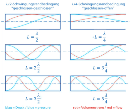
For a further analysis of the oscillation situation RohrLEx starts usually with the search after λ/2 and λ/4 resonances, to be able to understand the oscillation's boundary conditions.
λ/2 resonances arise in the piping system if at both ends the pipe is closed. In any case this is true for hydrostatic units and for closed valves. Examples of it are a pressure regulated pump which provides flow into a constant pressure system or a hydrostatic gear.
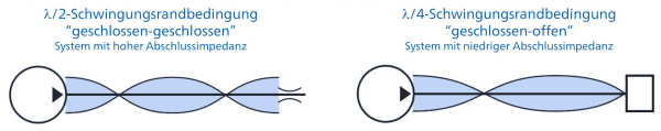
λ/4 resonances occur, if only one side of the piping system is closed, and the other side ends into in a large volume. This can be e.g. a pipe that leads into a tank or into a big hydraulic cylinder, or it can be an accumulator which is connected to the main piping by a branch line.
According to this theory the λ/2 resonance of the 8.1 m long example piping system, with a sound velocity of 1320 m/s, should lie at approximately 80 Hz. However, RohrLEx can already recognize a λ/2 resonance at 65 Hz. The higher orders of this oscillation should theoretically lie with integer multiples of the fundamental frequency, such as 130 Hz and 195 Hz.
The 2nd and 3rd oscillation order is, however, visible in the pressure vector plot at 157 Hz or 205 Hz. The cause of this shift in the sequence of the resonant frequencies is the subdivision of the piping in steel and flexible hose segments.
Even if the segments do have the same diameters the material change causes a change of the sound velocity in the respective segment. In addition, shifts of the system resonances arise if the piping system is built up from segments with different diameters or by parallel pipes. An exact analysis of the oscillation situation is then only possible by means of the procedure shown by RohrLEx.
What are the next analysis steps for RohrLEx?

After RohrLEx has an overview of the oscillation situation in the piping now, he can continue with the analysis of the line terminations. From a vibration engineering point of view pumps, motors, cylinders or valves are already classified as closed or open line terminations. However, the geometry of these components still must be taken into account. The internal channels, resistances and volumes of pumps, motors or cylinders have a clear influence on the dynamic behavior of the respective line termination. Since this dynamic behavior can superfluously change also depending on the oscillating frequency, one also speaks about the terminating impedance.
RohrLEx has learned that the consideration of the terminating impedances in the simulation is essential for a realistic pressure vibration analysis of hydraulic piping, and that only in such a way the design of suitable remedy measures can be successful. How RohrLEx measures line terminations impedances and represents them in the simulation this is another story, which RohrLEx for certain likes to tell, if opportunity raises.
The experiences of RohrLEx are also available as Flyer.